CP25E FSAE Drivetrain Structure Design
Written: 1/6/2025
I am currently serving as Cal Poly Racing FSAE's drivetrain lead as we work to design, build, and test the highest-performing electric vehicle in our club's history, and ultimately win competition. I used NX and ANSYS to redesign and analyze our vehicle drivetrain structure. My design's primary goals were to be light, reliable, and manufacturable. I defined design requirements, designed for manufacturability, learned how to construct a subsystem of many components, sized bolts and bearings, sourced off-the-shelf components, and integrated my design into the overall vehicle build.

Drivetrain Structure Assembly
I began my design by defining the requirements it had to meet. These designs came from top-level vehicle design and technical direction, reliability/serviceability, testing optionality, and performance targets. Over the 2024 summer, I presented these requirements to my team and alumni in our Design Criteria Review where I provided detailed rationale for each target.

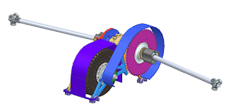
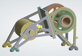
I then began designing and integrating my design in NX. The structure supports an Emrax 208 MV CC and FSAE Drexler differential while adhering to all FSAE competition rules. I selected 6061-T6 aluminum because of its strength, machinability, lightweight, and easy availability for our team.
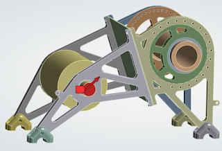
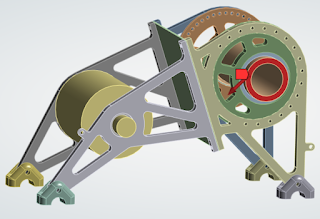
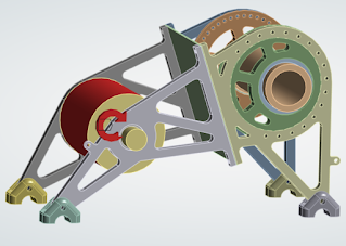
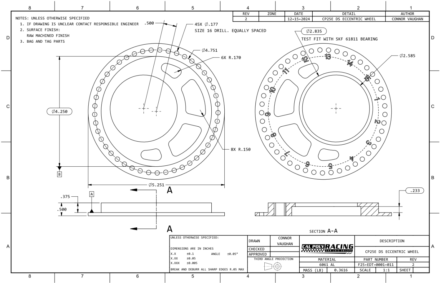
The structure is broken up into 4 primary mounting plates to aid assembly and serviceability by allowing either the differential or motor to be removed from the assembly without completely removing the other. The differential is mounted to the large plates using eccentric wheels which allow us to adjust its position by 0.5" in any direction. This adjustability allows us to apply proper tension through our chain. The design also features 4 chassis mounts which connect the primary drivetrain structure to the floor of our monocoque chassis.
[Images of plates and eccentric wheels with short descriptions and extra details in captions]
I brought my design into ANSYS workbench to complete both structural and modal analysis. I created simplified bodies for the motor, differential, bearings, and scatter shield to simplify the mesh and reduce solving time (I was concerned about the load on the structure rather than those components). I applied a design factor of 1.6 to all of my loads.
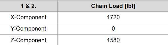
Max chain load in each direction backed out from my acceleration sim and structure geometry
The load applied to the motor output shaft and differential (where sprockets are) in opposite directions
Acceleration vector in ANSYS
Motor torque resolved through the structure
Torque applied to the simplified motor body
Torque applied to the simplified motor body
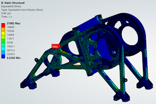
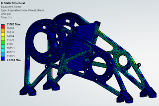
I completed an equivalent stress analysis to ensure my design had no major stress concentrations and appropriate pocketing to withstand load cases. I also verified that T6-6061 aluminum was an appropriate material selection for this design. Results:
FEA Output
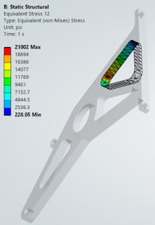
Local max stress location. 0.9 margin of safety
Local max stress location. 0.9 margin of safety
I analyzed the deflection of my design to ensure the alignment between the sprocket on the motor shaft and the differential was less than the maximum values as defined by my design requirements.
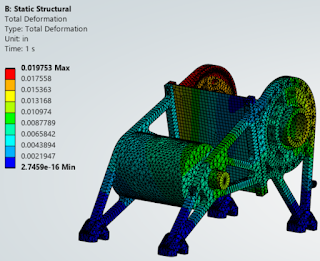
Overall Deflection (0.01975 in max)
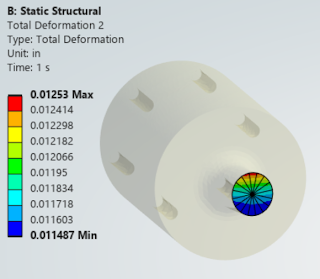
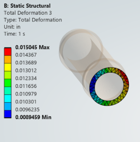
Deflection at the location of each sprocket
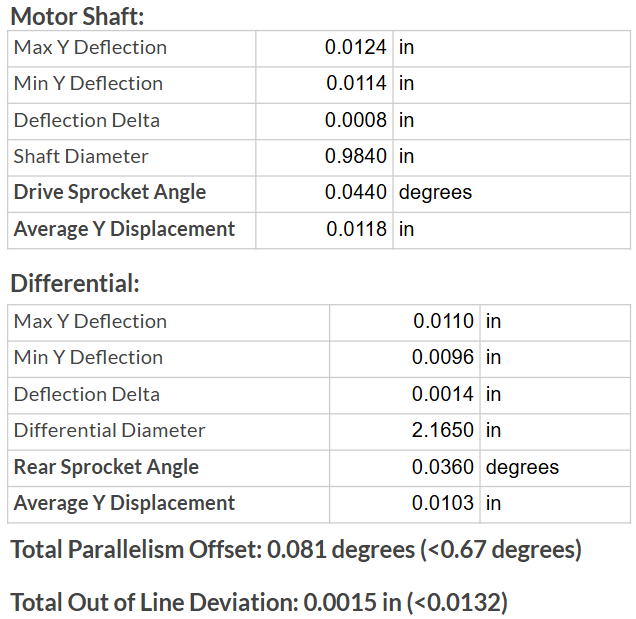 Calculations using deflection values to determine parallelism and alignment deviation. Both were within the required range.
Deflection at the location of each sprocket
I also conducted a modal analysis to ensure the vehicle's vibrations (mainly motor rpm) do not reach the fundamental frequencies of the structure.


1/17 - 1/19//2025: Eccentric wheels complete and primary structure manufacturing progress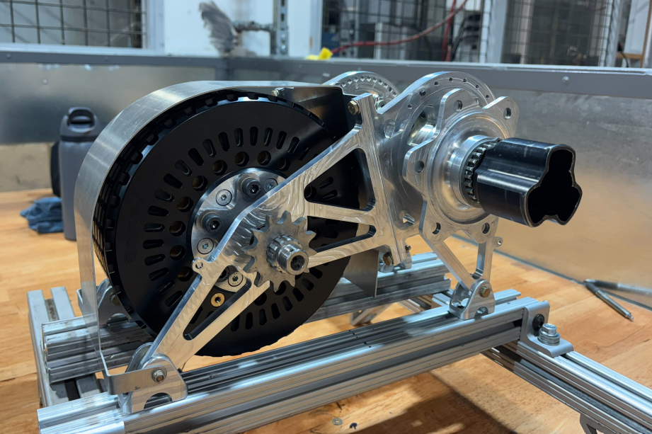
The first mode occurs above the minimum frequency defined by design requirements (205 Hz)
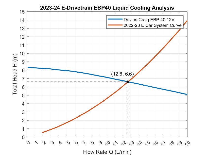
For a further detailed look into my drivetrain structural design as well as cooling analysis and vehicle performance analysis, I encourage you to look at my Critical Design Review slides found here.
Updates:
Updates:
12/17/2024: The first operations of the eccentric wheels were completed by Cal Poly Racing's incredible CNC machinists!
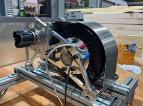
1/26/2025: First assembly for bench testing

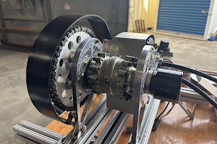


2/20/2025: Final assembly and vehicle integration

Comments
Post a Comment