Updated 1/7/2026.
In my second year as the Cal Poly Racing Formula SAE Electric Drivetrain Lead, I refined a previously successful drivetrain architecture developed for CP25E (see CP25E FSAE Drivetrain Structure Design). This iteration focused on improved structural performance, serviceability and modularity, and tighter integration with the full vehicle system.
Drivetrain design and analysis were carried out using Siemens NX for CAD, ANSYS for structural and modal FEA, and MATLAB/Simulink for performance and load modeling. This writeup overviews the design evolution, analysis methodology, and early manufacturing progress completed at the time of writing.
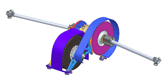
Figure 1. Driveline structure and half shafts overview. Select component drawings are included at the end of this document to illustrate design detail and manufacturing considerations. The complete drawing package is not publicly shared.
Analysis Roadmap
Being the Electric Drivetrain Lead. there are three main areas I am solely responsible for on the vehicle: driveline structure, cooling, and performance. High level modeling and requirements guide preliminary analysis and component selection which then feed down into subassembly requirements and analysis.
This writeup primarily focuses on the structural analysis and manufacturing of the driveline. The overall analysis hierarchy and workflow are summarized in Figure 2.

Figure 2: Drivetrain analysis roadmap/flow down
Driveline Structure
Similar to the CP25E drivetrain, the revised design shares the same modular (motor half & differential half) design mounted only to the floor plane and using eccentric wheels for chain tensioning. Key improvements that were made were:
- CG reduced from 8.05" to 6.18" with the differential at its highest position
- Motor & differential packaged 0.6" closer together
- 24% mass reduction on driveline components
- First natural frequency increased by 12.5% (to 180 Hz), providing a 55% margin from peak motor excitation
Figures 3 & 4. CP26E final design
Peak chain loads from my longitudinal acceleration sim provided the primary load the structure will experience, which was used for initial member sizing and bolted joint calculations.
Figures 5, 6, & Table 1. Bolted joint hand calculations from a 1300 lbf peak chain load.
The CP25E redesign did not include eccentric wheel optimization, which were initial designed for a 520 chain. By downsizing to a 420 chain, which has a shorter pitch, we reduced chain weight and the amount of eccentricity needed in the wheels from 0.5" to 0.3125", allowing for the entire package to be reduced.
Figures 7, 8, & 9. Eccentric wheel revision overview. Blue = old, pink = new. The left overlay shows the drive side comparison, the middle overlay shows the passenger side comparison, and the right overlay shows the slight increase in thickness from 0.375" to 0.4".
I performed a linear FEA model using ANSYS to evaluate the structure under peak acceleration loading and peak regenerative braking loading. The setup and results of that analysis are shown below:
Figures 10 & 11. FEA geometry with simplified bearing, differential, and motor bodies (with equivalent weights). Steel beam elements were used in place of bolts (8x).
Figures 12 & 13. Fixed supports through the bolt holes of the chassis mounts. Frictional contacts between the motor and differential side pinch bolts, and no separation contacts for the bearings.
Figures 14. Acceleration load case. 1400 in-lbf torque applied to the motor body, max chain load of about 1400 lbf applied to sprocket faces, 825 lbf preload applied to each AN4 bolt beam, and an acceleration envelope of 1.2g in X and 2.4g in Y.
Figures 15. Regenerative braking load case. 475 in-lbf torque applied to the motor body, max chain load of 450 lbf applied to the sprocket faces, 825 lbf preload applied to each AN4 bolt beam, and an acceleration envelope of -2.25g in X and 2.4g in Y.
Figure 16 & 17. Von-Mises stress results from the drive side motor carrier.
Figures 18 & 19. Von-Mises stress results from the drive side differential carrier.
Figures 20 & 21. Von-Mises stress results for the front right chassis mount, and the drive side eccentric wheel.
Table 2. A summary table of the final margins for each component under both load cases.
Figure 22. Overlay of CP25E (grey) and CP26E (blue) driveline structures. CG reduced from 8.05" to 6.18"
The primary modal consideration on this driveline was avoiding resonance from the motor's rotation. The target was to have a first natural frequency of the driveline structure to have a 0.5 margin from the peak motor rotational frequency (7000 rpm, 116 Hz). This was also validated using ANSYS modal analysis.
Table 3 & Figure 23. A table of the first 6 natural frequencies, and the mode shape (horizontal bending) of the first mode, which is 55% above the highest excitation frequency.
Manufacturing
At the time of this writing, the CP26E drivetrain is being machined in house in the Cal Poly Shops. The first component to come off of the CNC mill was the eccentric wheels. My team preformed a detailed First-Article-Inspection of these components using the Cal Poly CMM, to verify the final part met its intended design specifications.


Figures 24 & 25. Eccentric wheels before the final operation and after completion.
Figure 26. CMM inspection being preformed on the Drive Side eccentric wheel.
Figure 27. Drive side eccentric wheel part drawing, with boxed and lettered measurements for inspection.
Table 4. Drive side eccentric wheel FAI results (green = within spec).
Figure 28. Drive side differential carrier for CNC manufacturing and post machining inspection.
Figure 29. Drive side motor carrier for CNC manufacturing and post machining inspection.
More drawings may be available upon request.


Comments
Post a Comment